>
YAMAHA
STRINGS
SS-30
RACK-MOUNTED WITH MIDI
MIDI STRINGS

Wednesday, December 20, 2017

Amazona.de Article


It's nice to see the hard work researching and documenting my journey into the SS-30 get some recognition...

Der Yamaha SS-30

Every now and then I decide to Google the SS-30 and see if anything new has come up. Usually, it's just an auction, but sometimes there is a new article mentioning the SS-30.

Yesterday this came up:
https://www.amazona.de/blue-box-yamaha-ss-30-string-synthesizer/

Here's the Googlish translation:
https://translate.google.co.uk/translate?hl=en&sl=de&tl=en&u=https%3A%2F%2Fwww.amazona.de%2Fblue-box-yamaha-ss-30-string-synthesizer%2F 

Amazona is a German website dedicated to synthesisers and this article is written by keyboardist Costello. I'm very pleased to see that he has quoted this blog and credited me throughout!

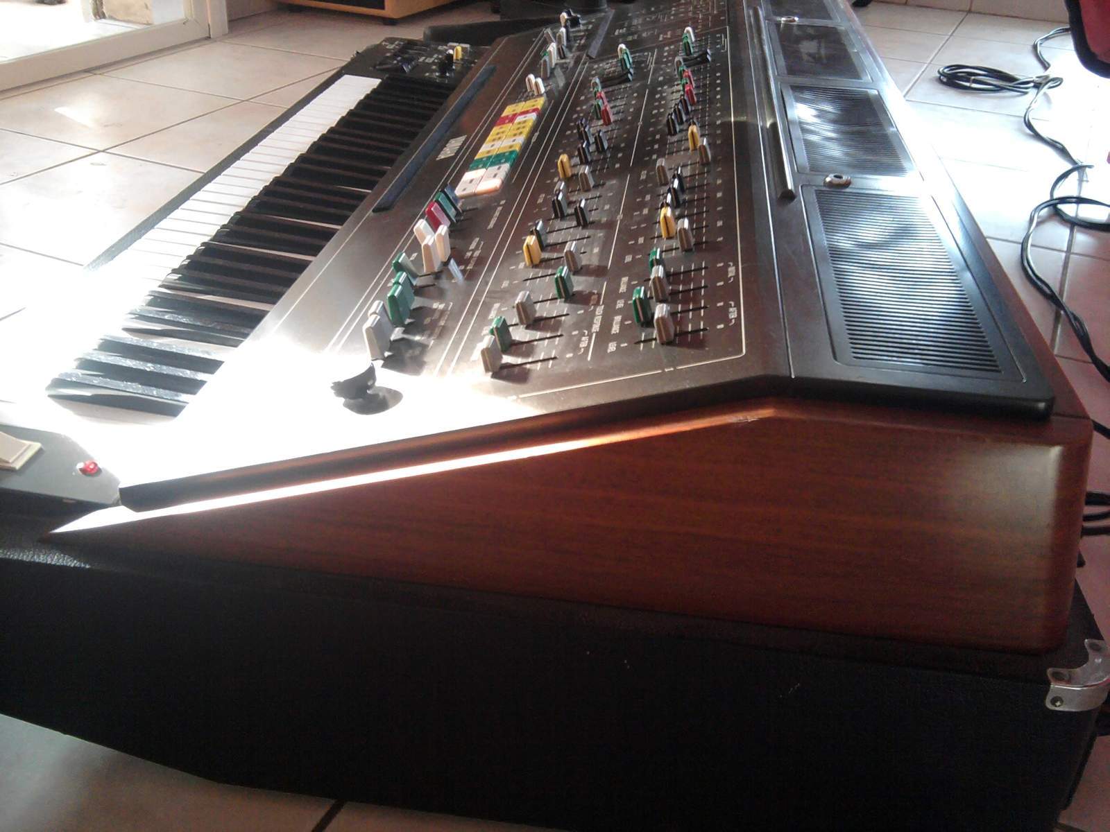
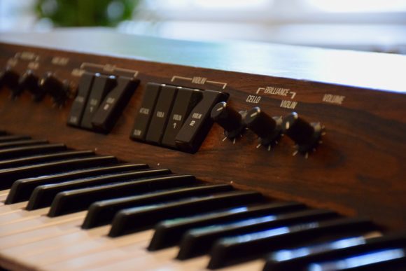
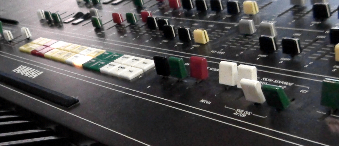
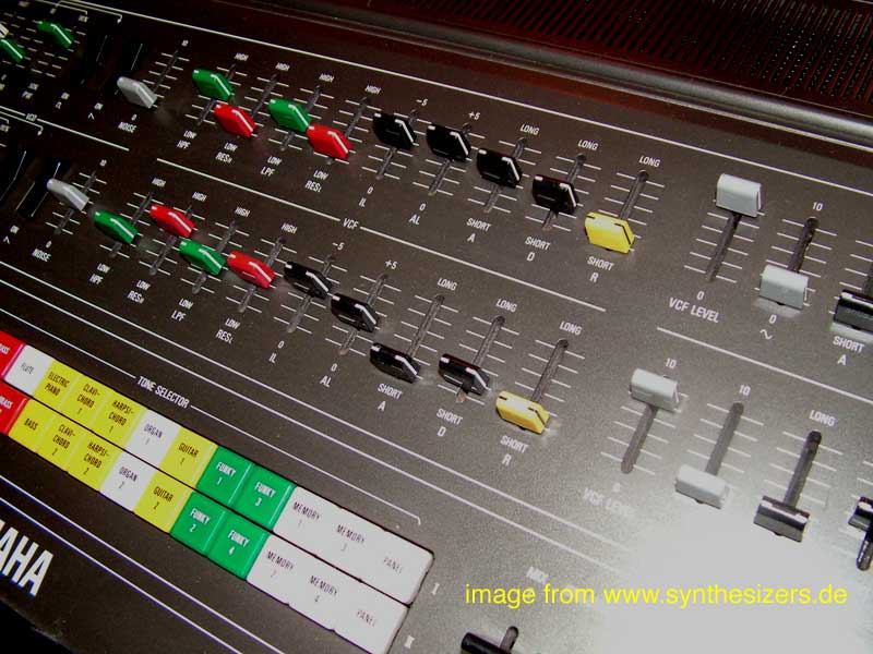
Costello's SS-30 in close-up

Found in translation


The Google translate does a decent job and it's quite readable. Even where it's a bit hard to parse it still makes sense.
"Those with the organ made rock, with the string part epic-spun "pothead music" - no play under 7 minutes."
My favourite quote though is:

"Steven Norgate dedicated his own website to the instrument, where he documents his self-imposed goal of the (very elaborate) MIDI-coding of the string synthesiser"
Don't forget about the crazy the rack mounting!


Costello talks through his early desire for a strings machine which is then rekindled by seeing Ultravox live in 1981. He is a fan.

Then he goes through the competitors and the market for stringers before getting down to a detailed description of the functions - laying out its strengths and weaknesses.

He notes that the violins are better suited to the Orchestra effect whilst the Cellos are surprisingly good without and work as a bass synth part. This is where the selection of which one to send through the effect is crucial.

He then reviews the use by Ultravox and Dave Formula and via him to the current market value and his own recent purchase. With a nod to the unobtanium chips the review is over and I have to say its the best yet - if only because I have covered most of the same ground already! 😉


Just a Limit


Let's take those limitations one at a time:


Shrill violin

I can't argue with that, but there is the Brilliance control and with the Orchestra and with a good measure of reverb it's basically fine. Costello's comparing with the Solina and other stringers - so it's all relative.

Only does strings

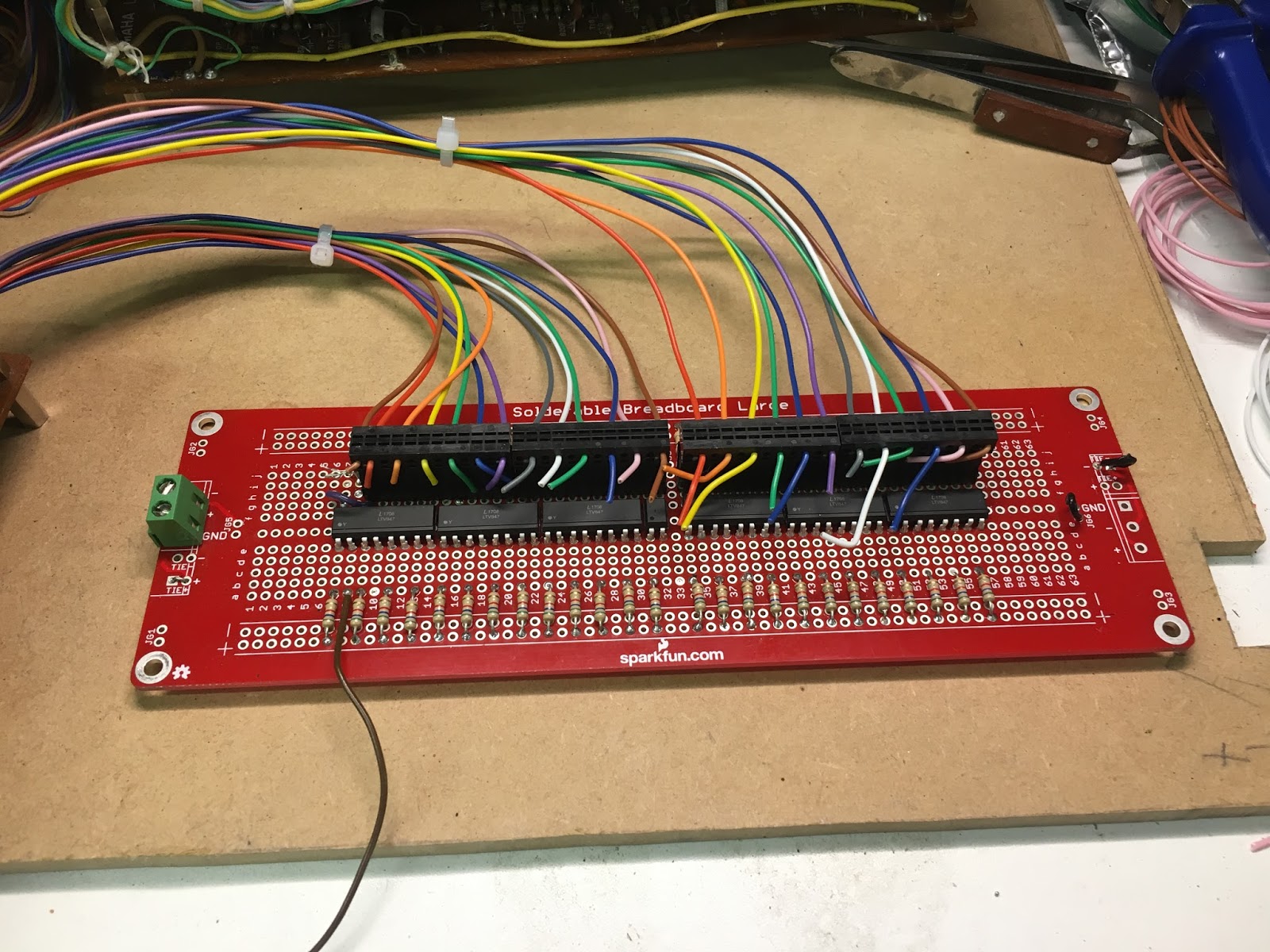
True. A few times I've thought about what it would take to try and tap-off a sqaure-wave voice from the dividers. Apart from the ridiculous amount of wiring involved it just isn't worth the effort though. There would be no enevelope either.

Only fast/slow control for the attack

 True, and I've looked very carefullly about how to modify that, but it's more of a re-design job than a modification. I have a whole post about that limitation in the works.

Noisy Orchestra effect

Not a problem unique to the SS-30 though. Gating and eq'ing can help. It might be possible to clean it up with some newer components, but I haven't ever thought it was bad enough to warrant that kind of intervention.

Mono only output

This is something I have thought about addressing already, in this post. It's quite possible, but will need a bit of extra output buffer amplification.

No separate output for violins and cellos.

I've only considered this briefly in the past, but couldn't see much to gain from it. Costello is clearly interested in putting different effects on each voice though, so should I reconsider it? I might. It depends on the levels, but there is an obvious place to feed the voices from, just before the Orchestra sedtion. And I'm going to be rewiring there anyway, so it makes sense...

Orchestra depth

Also, in the comments section, another person previously quoted in the article, 'iggy_pop' notes that "the depth of the chorus modulation (never enough)". As I noted in the Orchestration post the so-called depth setting on the SS-30 is mix depth, not the modulation depth. However, I can add a control for this LFO/modulation depth, but it would not increase the amount of modulation. Do I need to see how it might be boosted as well as cut?  I will take a look at the voltage out of the Phase Mixing section to see how much is being swung on those outputs.
If he was actually talking about the LFO rate, then I can probably do something there as well. The rate is limited compared to the Yamaha CS-15, which uses the same oscillator chip.


It's A Demo


But wait, there's one more treat in store! Costello has created fifteen tracks using the SS-30 to demonstrate the versatility of the old beast. Picking up styles from the likes of Pink Floyd, Genesis, Ultravox, John Carpenter, and other late-seventies influences, he uses external effects from the same era to show what the SS-30 sounds like in a variety of settings.
There is a mixture of full tracks and parts showing off certain features, such as the detune. The use of a good reverb is well noted and is something I have been considering for the long-term.

 Marvellous!


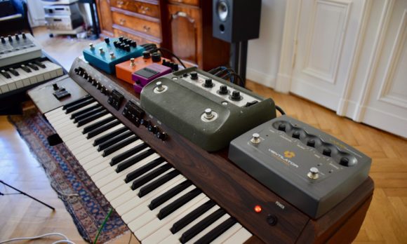
Costello's SS-30 with a bunch of vintage and vintage style FX pedals


Wednesday, October 18, 2017

Orchestration

Let's look at the Orchestra. Firstly I was interested in a new DIY product from Oakley Sounds which leads me on a diversion around the Roland Juno chorus. Then I talk about the controls I will need for the SS-30M.

Oakley SRE330 - Enhanced Stereo Ensemble and Chorus Module


I just saw this new DIY chorus project available from Oakley Sound and it got me thinking about the Orchestra (AKA Ensemble or Chorus) part of the SS-30 again.
They also used an alpha Juno for the demos, which is also kind of interesting as I have an MKS-50.

The Oakley design has 4 delays which can be stacked or and split for stereo in various combinations, It has two basic settings.
"The three phase setting replicates the action of classic string machines originally from Europe such as the Solina and Logan String Melody."
And
"The Multimode setting is designed to replicate the actions of various classic synth chorus units and string machines from Japan."
A-ha! Like the SS-30? Not quite, no.

The multimode has three settings
  • Quad Ensemble
  • Dual Ensemble
  • Stereo Chorus

The SS-30 is mono and the quad ensemble uses all four delays, whereas the SS-30 has just 3. In fact the SS-30 is closer to the three-phase mode, albeit with fewer phases.

You may recall from this post that the SS-30 has two LFOs with two phase shifters
So, that's two LFOs, although one is variable and only two phase shifts but the mixing is complex. It's not even clear from the Oakley description how they mix the phases in 3 phase mode, so I can't actually tell how they compare.

Overall it looks like a very nice project and one that I would be prepared to consider doing, but probably after the SS-30M is done.

Juno what chorus the Alpha has?

As mentioned above I have an Roland MKS-50, which is a rack-mount Alpha Juno. The chorus on the Alpha Junos/MKS-50 is apparently a different beast to that on the older Junos. Gordon Reid summed it up as "more flexible but less rich". And rich is the desirable thing, really. You can change the rate of the LFO (or LFOs?) but is that better than being able to switch between two LFOs? I would say the chorus on the Alpha is in keeping with the more restrained and cleaner sounds which were in vogue at the time. But, why is it like that?

The Alpha's chorus is a stereo-pair of single BBD delay lines. The MN3101 is the clock and the BBD is the 256-stage MN3009. And the Juno-6? The same! They use the same exact chips. There are two identical circuits, so you get stereo outputs. The JX-10/MKS70 had more-or-less the same design as Alphas too. So what was different?
The Juno 6 service manual helpfully makes it clear that there are three triangle-wave LFOs. Two at chorus speed of 0.4 and 0.6 Hz and a vibrato which is added at a lower level and runs at 8Hz. The schematic is a bit loopy by I think the same modulation LFO mix is is fed to both channels but out of phase.
On the MKS50 things are not as clear. There seems to be a single signal split into two out-of-phase signals driving the clock. The signal's origins are more obscure though. It appears to be digitally sourced from the CPU via a gate array and a multiplexer.
The gate array has a D-to-A converter built in and its here that the data from the CPU is converted into the LFO signal. On the block diagram, the multiplex is labelled as a sample and hold (S/H) and there is some kind of active filter after that - which makes sense, as there is no continuous CV to make up the LFO. It is smoothed out by the filter, I guess. The notes refer to it as chorus LFO and Chorus Rate CV.
In notes there is also basic diagram of what to expect.

Those arrows seem to indicate some sort of pulse-width is adjusted but I guess this is actually the frequency/wavelength.

It's possible to add a chorus input to the MKS-50 but there's a little debate about the wisdom of doing it and I haven't seen a really popular modification for it. Apparently there was a professional modification around, so enough people must have thought it was worth the effort of tapping into it to make that a thing. There's no info on what they did though.

Conducting The Chorus

In my mock-up, concept art panel design I had replaced the Orchestra section's Violin and Cello switches with faders. Looking back I'm not sure I knew what that was actually meant to do. As there is also a Depth control what was I thinking? Would the depth control also be required? What would the effect of the control be exactly and wouldn't those faders be pointless if the depth was set to zero? I honestly wasn't sure. And then the switches started to misbehave...

I don't  think I had ever looked at the schematic for the orchestra controls in any great detail and when the Violin switch started to behave strangely I realised it was doing more than I had imagined.

Mix Depth

To start with, in the Off position the switches bypass the Orchestra completely. In this mode the depth setting has no effect on the sound at all.

This might seem pointless at first sight. It's generally less confusing if all controls work at all times and there's no context in which they aren't having some effect. In this case the context is whether the switches are on or off and the key here is that there are two switches and two sources that pass through the orchestra effect. There are, of course, four options here and only one leaves the Depth control redundant. Still, it does return us to the question of what my two faders were supposed to be for.

Next, if one switch is on and the other is off there's a way to have one voice dry and one wet. This is why there are two switches.

If either switch is in the On position the Depth control sets the mix of wet (effected) and dry (unaffected) signals for both Cello and Violin. This means that unless one is completely off, there is no way to set the mix independently. You cannot have one at 50% and one at 100% wet, for example. Now I think I can see the point in the faders. If they controlled the amount of mix for each voice then there would be more control. However the depth control would be redundant. And yet there is another option.

LFO Depth


Referring back to the Oakley Sounds SRE330 there is a depth control there too. However this Depth control is not the mix, it's the amount of LFO being applied to the BBD. So, could I rethink the depth control as LFO depth?

There are two LFOs. And then they are mixed together and the result is three signals which go from LF board to the OR board. I could easily intercept these wires and send them through a 3-gang potentiometer. Or I could have a depth control for each of the two LFOs - but then I would have to pull up some resistor and I;m not sure it's what I need anyway.
I reckon the LFO depth would be a good change. Along with the LFO rate settings I thought through in the previous post on the chorus I'm starting to get a better idea of a more fully featured Orchestra/Ensemble/Chorus effect. 

Switches to Faders?

If that's it for the mix depth control, there could be two fader controls to set the mix of wet/dry of each voice. Can I achieve this just by rewiring the existing connections though?

Unfortunately Yamaha took a design decision which makes that harder than you would think. The switches are actually double-pole (two switches which are actioned together at the same time). The first pole, on both switches, switches the incoming Violin and Cello signals to either a mixer which then passes them on to the Orchestra, or to another mixer which then passes them onto the other pole of switches. At this pole the mixed signal either goes directly to the output stage or to the Depth control.
To be clearer if only Violin goes to the Orchestra, Cello goes to the output stage directly and Violin goes through the Orchestra and to the depth control. The depth control is then mix of the dry Violin and wet Violin from the Orchestra.
I need to somehow have the completely dry, bypass signal at one end of a potentiometers and the Orchestra at the other. The incoming signals will then be sent to one or the other, or some mix of both. Then the output of the bypass would go direct to the output and the Orchestra would also go direct and and the switches and original depth control would be completely redundant.

Looking again at the diagram I simply removed the switches and Depth control then drew in what I wanted to do. 


After the Buffer section and before the (pre-Orchestra) Mixing Amp and Mixing sections I have replace the switches with two potentiometers. I will have to experiment with the values here.
After the Mixing section I have labelled the path to the next section as 'Bypass'.
The output from the Mixing amp is split two ways. One goes to the Orchestra board and the other to the mix Depth control. Now the one to Depth control line redundant. Instead the signal back from the Orchestra goes direct to the next section where it is mixed with the Bypass signal.

I will need try this, but it's mostly just disconnecting the switches and Depth controls then adding the sliders. It's not a big job. My main concerns are how well the inputs are balanced between bypass and whether having the orchestra always switched in makes and difference to noise levels.


External Input? 

One idea which has been in my mind for long time - and is again fired by the Oakley SRE330 - is to have an external input on for the Orchestra effect. I makes perfect sense and in terms of the value of the finished article will mean I have a top notch chorus effect available even when I'm not using the SS-30M strings. All it needs is an input jack and maybe a level control. It's something else to try, and whilst I have the wire's loose it make sense to at least try.

Summing Up


In summary:

  1. Need to test out the ideas in the previous post about adjusting the chorus rate and making it controllable - LFO Rate
  2. Insert a control on the amount of LFO reaching the BBDs - LFO rate
  3. Remove the switches and Depth control and replace with a mix-depth control for each voice. 
  4. Test an external input


Friday, October 13, 2017

Live Update

Real-Time Operating System

I have played live! For the first time (well, almost) I went out and played to a small group and it went fine. This was a totally new experience for me, playing not only live but with mostly my own compositions.

Shadow Factory is my studio project


Now it's done I'm considering my next move. I think I want to record some of the tracks I played properly and then I'll probably try and keep up a regular process of updating and writing new stuff for a potential new gig at some future time.

Here's what I took, and you can see the set-up below.

  • MAM - Freebass 383 (TB-303 voice clone)
  • Roland - System 1M
  • Roland - System 500
  • Mutable Instruments - Braids (home made)
  • Expert Sleepers -  Distings MKIII (unused in this set)
  • Make Noise - Function
  • Mutable Instruments - Kinks
  • Mutable Instuments - Ripples filter (home made)
  • Plankton Electronics - Jellyfish V2 Analogue Delay
  • Doepfer - a138m Matrix Mixer
  • Fostex - DE1 Dual MultiFX
  • Behringer - Pro Composer
  • Roland - A880 MIDI Patchbay
  • Arturia - Beatstep Pro
  • Arturia - Keystep
  • Korg - Volca FM
  • Korg - Volca Sample
  • Korg - Beats (modified snare and indivdual outs)
  • Behringer - Xenyx 1202 Mixer

Real-Time Operating System is my live project


Friday, September 15, 2017

2017 - Wrapping up for another year

Time's up! The summer here is over. Yep. Three months and we're done.

I could have done more, but the rest of life gets in the way - which is only right. This is a hobby project and one amongst many other interests. I've also had to carry out a few unforeseen repairs which slowed things down a bit.

There is a bit more warm weather left and I could get a heater for the garage but something else has come up which I need to focus my energy on. I'm breaking the habit of a life-time and playing music live. It's less than a month away now and I really have to get my act together. By the time that's done it will be mid-October and, well, we'll see.

What I have done this year
  • Fixed noise and other issues
  • Built interface and played the SS-30 via MIDI
  • Started a front-panel design.
What I also wanted to have done this year:
  • Sort out the power supply for the interface
  • Fix up a solution for the power supply, MIDI and audio connectors on the back panel.
  • Fit everything in the enclosure and fix temporary front-panel to it as well
If I'd managed that I could have taken the SS-30M inside for the winter and, y'know, actually played it. Well, some of the front-panel controls aren't working very well. The Orchestra section switches in particular are failing. This is my fault for not looking after them properly but it's another hurdle.


What I did that you can't see yet (aaaah!)
  • Bought components for the front-panel 
I'll save that for another few posts on the subject of knobs, sliders, switches and, err, cannibalising old Yamaha organs (ahem). Oh yes!


Build-a-board


Let's build this thing!

First board with Lite-On opto-couplers placed ready for soldering.


The first problem I encountered was that my lovely connectors were too big for the wires on the K-boards. I had to go and order another batch of wires and then add new wires from the K boards to the connectors. This took a lot longer than I was hoping but I had no real choice.

Lotsa, lotsa wires.
K1 and K2 boards wired to connectors on the first interface board.


Much soldering and wiring later I had the first board (err) wired up and - somewhat to my surprise - all working perfectly.


The first interface board wired up to the MIDI decoder

MIDI IN


I ploughed on to the second interface and suddenly I had a MIDI controlled SS-30!


MIDI Interface almost complete


 So, I'm almost there. I have to sort out the power to the decoder now though. So far it's been run of a bench PSU and I hope to get it running off the SS-30 supply. Thats' another post though.

I meant to get a recording of the whole thing being played, but it's not done yet so I'll end this post on that tantalising prospect.


'Opto-mum' Currents?

This post is a bit behind events now (more on that to come) but here it is anyway.

'Opto-mum' Currents?

Before I launch into building the coupling boards that will interface the MIDI decoder to the key switches I need to actually do a bit a electronics design with equations and everything! The first task is to ensure that opto-couplers have enough current on the input to make sure there is enough current on the output. The input is an LED, so if the current is too low the light emitted by the diode will not be sufficient to turn on the photo transistor fully. In that case the voltage drop across the phototransistor will be too low and the switch will only be partially on. It might be enough to hear something, but I don't want a quiet SS30.
The second task is to limit the current to each input so that the cumulative load of the switches is not drawing hundreds of milliamperes. With 49 keys the potential is there to simultaneously draw more current than the power-supply can handle and blow the fuse. The power rails on the SS30 are rated up to 500mA and if possible I want to use the +15V supply for the MTP8 and the couplers.
Therefore I need to find the optimum current for each optocoupler input - not too low and not too high.

MIDI Decoder 

The MTP8 draws around 15mA for it's own logic etc.
The maximum current per output in the MTP8 is 500mA. But, each group of 8 outputs is limited to 2A which translates to 250mA per output with a possible maximum for 49 keys of 12.25A(!). All that means is it can comformatbly handle large currents. But I want as low a current as possible.

K Boards

The K boards key-switch 'input' is held at -7V through a 3.3K resistor. That means we should getting around 2mA through each switch.


KS-M-C3 is what goes to the key to be switched to ground

The measured value I got from one I picked at random was over that so my calculation must be mistaken somewhere.


And, hey, look! That's my new multimeter.

2.37mA means that the voltage is actually higher. I usually measure around 7.7V which results in a current of 2.33mA, which is much closer. In any case I measured approximately 2.4mA so that is my target output current.


Opto-Coupler Characteristics

Transistor outout optocouplers have many charascteristics but the main one I'm interested in the CTR. The Current Transfer Ratio - expressed as a percentage - simply decribes the relationship between the input current to the LED and the output current. This is essentially the gain of the coupler. All I have to do is make sure that the gain is 100% and they will be no loss through the output, thus mimicing the elecro-mechanical switch I'm replacing. But, what if the gain is a lot greater than unity? Does that mean that somehow the current through the going to be higher? Err, no. The current cannot be any higher than the 2.4mA I measured, but you can have a CTR above 100% because the input current can be lower than the output. This is the kind of coupler I need because if I had to have 2.4mA available for every input I would need 118mA to cover the entire 49 keys. I want to target 50mA or 1mA per switch. 


When I set up the single octave test I had just grabbed some opto's from Maplins - Vishay IL74s - without looking too closely at this CTR characteristic.
The IL74 - data sheet here - has a quoted typical CTR of 35% for 16mA. But the datasheet also shows that it ranges above 100% when the current is greater than 20mA. To be honest I worked through the datasheet and it was a very long and boring process which required this guide on how the CTR graphs should be interpreted. Vishay take the long road and I'm not interersted in that here, so instead here's the shortcut.
I was using 1K current limiting resisistors with a 15Vsupply in that test. The input current (If) was then measured as 13.34mA (the voltage drop across the resistor being 13.34V). A lot higher than I was looking for but that comfortably switched the keys on. The effective CTR in that case was then (Ic/If) 2.34/13.34 x100 =  17.54. Experimenting with other resistors and supply voltages I managed to get good results with 9V through 1K2. This was 2.59mA If and 2.08mA Ic giving 80% CTR. However I couldn't do any better and I want to get the input current down to more like 1mA. This would require a CTR of  234%.


The LiteOn LTV-847 has minimum CTR from 50% (for 5V/5mA) but a maximum of 600%, which seems much better than the Vishay part, and they are quite cheap, so I ordered these.
Avoiding the datasheet again I worked through a series of resistsors from 1K to 10K and measured the input current and output voltage drop. I was looking for the point where the input current is low but not so low that the output current is throttled and the voltage drop across the output collector emitter is rising.


Since taking these measure I seem to have lost the info what the supply voltage was. Was I used 9V or 12V or what? Ah well. When I go the 6K8 resistors I decided they were too high and although the voltgae drop shoudl have been relatively little i t was much higher. May be I changed the input voltage? In any caseI decided to change to 5K6 and as I had enough 'in stock' I used those instead. It was time to start building!


Thursday, August 31, 2017

Billy Currie talks String Synths and Ultravox


Big, exciting updates on the SS-30M progress coming soon!

But in the meantime, here's a very interesting video from GForce Software. Billy Currie (of Ultravox fame) talks about stringers with reference to the Elka Rhapsody and SS-30 in particular. He describes how both were used on the smash hit Vienna for different parts, their relative strengths emulating real strings and the feel of each.The video is to promote the Virtual String Machine/Re-Strings plug-in emulation of strings machines,


In the video Billy is at the GForce studio and is playing the mother of all string synths - the Freeman String Symphoniser.I might have to write something about that one day (and correct a few of my mistakes).


I've written some commentary on what he's saying as it's just a general chat really and some of the points fly past pretty quickly. I then took the opportunity to write an analysis of how the SS-30 and Rhapsody were used on Vienna "of course you've got to talk about Vienna".


So Much For Solina

Ultravox were doing experimental things so they decided to get a strings machine. I'm not sure quite what that means, but I think this would be part of a general move towards electronics. It was the Solina they got first though. Billy doesn't like it because it was 'so weak'. He was not impressed! "Very middle of the road" and a "Mantovani" type of sound.

So then they got the Elka Rhapsody. The Elka had an "emotional" character. This matched his interest in German classical music gained at music college - Schoenberg, Bartok etc. And by extension then Kraftwerk and the "emotional and lost" feel. In Particular on The Ascent - from Rage In Eden


This string's something to me. 

Violinistic


For Vienna the SS-30 was used on the chorus because it was violinistic (that this a word, btw). What Billy wanted was the right envelope because as a violin player he wanted to play it like a violin.  It was obviously to Billy's liking when compared to other stringers for this reason. He sings and mimes the way a violinist would play to better describe the effect.
As he says: "You could do a very slow fade in" and "You were able to create the feeling of a bow". The SS-30 attack is actually quite short, even in the 'Slow' setting, but we're dealing with the articulation of a bowed string, and not a slow fade in.This was in contrast to sustaining the notes as suggested to him later by the guys from Mellotron (Streetly?).

I think it's quite hard to hear what he's talking about on the first two choruses though. He's specifically referring to the melody, which is picked out on piano. The strings are following the piano part but the piano dominates your attention. The strings are more washy. You need to pay a bit more attention to notice that they are following the piano. I think that's because they first sustain into chorus and then out to the "Oh, Vienna" line. You are somehow distracted from the way they articulate in the melodic phrase. The final chorus is more definitive though and this time you are left in no doubt.

In a way it's similar to how ABBA used the SS30 on Gimme Gimme. It's right there, in the hook, but as an undertone. 
In this video you can see Billy playing the part on the SS30, which gives you a better idea of what he was doing - the sound is quite poor on this though.


He doesn't really mention the bridge into the chorus, which is arguably a slower attack. This is more of a swell though and I wonder if the volume pedal was used here.


Middle String Section

 The middle section is preceded with an instrumental version of the verse. The piano takes the lead here with a single high pitched sting over the top. It's not clear which stringer but the higher parts tend to be Elka.
Then the middle section proper starts with a cello from the SS30 - "Great sound". This is the simple descending figure underpinning Billy's violin part. The attack is slow and it tucks in behind the beat to counter the synth bass line. 


I have to agree that it does sound very authentic. Very wooden.
 Then the orchestral part which comes in next is the Elka. I assume this was chosen here because of the feel. The sound is somehow 'shinier'. And then you can contrast it with the SS30 which comes marching in for the climactic final chorus. The SS30 sees the track out with one last sustained chord.

There you have it a pop masterpiece helped along by the SS-30.

Tuesday, August 01, 2017

Connecting you to the Switch Board

All-a-board

I have found the solution to my key switching PCB worries. After the quick lash-up I did on a breadboard I started to fret about what kind of permanent, solderable board to use. A standard Veroboard or matrix perfboard was the obvious answer, but only with a lot of soldering. I didn't want to have to cut dozens of wires and tracks and link everything together by hand, or rely on solder links. I also wasn't keen to design custom PCB. Apart from the costs the learning curve for creating a PCB is not one I wanted to commit myself too. If only there was a PCB just like a bread board, I thought. Well, apparently, there are! There's several on the market in fact, but I found one that matches my needs the closest.


This is the SparkFun Solder-able Breadboard - Large PRT-12699

"a real FR4 fibreglass board, with soldermask, plated through-holes, and the layout duplicates the connectivity of a solderless breadboard"

You can lay this board on top of a breadboard and insert the components through the PCB to test everything as normal. Then you can lift the PCB up with all the components already in the right place and you just have to solder them in.


Features/Specifications

  • 63 split rows
    • Like the breadboard there's "twin rows of 5 holes each, spaced 0.3" apart, to accommodate DIP ICs."
    • And there's an additional line in between the rows, but I might not need that.  
  • The holes are 0.1"/2.54 mm pitch (apart)
  • The hole size is 0.040"/1.016mm
  • The rails can be hooked up at either end 


Board Layout


I will need two of these large sized boards which will accommodate twenty-four and twenty-five key switches. With 16-pin, four-channel opto-isolators there will be three per octave (with one extra on K1 for the extra ). That's six 16-pin ICs per board needing (6 x 8) forty eight rows. K1 will need an additional single-channel 4-pin device. This will leave room to spare on both boards.
I might use some of this extra space for power rail circuit to the MTP8. A regulator is all that's needed if I can use one of the rails from the SS-30 supply. But that's another post...

The design then is simple. Every other pin on the opto-couplers will be an input or output wire and the alternates will be a resistor to one of the rails. What could be easier?

I have created a diagram of the layout in Excel  - here's the first board. Note that as this has 25 keys I'm going to reuse a spare connect on the connector and then have to cut a track (column h, row 9) on the board and link it to the correct one.


Getting A Good Connection


The only construction concern I have is how to get the wires to the board. The 8 strand wires from the K boards are around 0.7 mm with insulation but the conductors are approximately 0.5mm. That's probably 24 AWG or maybe less.

The options are:
  • Solder wires directly through the PCB holes 
  • Use some sort of pin or tag soldered to the board to solder them to 
  • Terminal blocks to hold the wires (screw or spring clips)
  • Use some sort of IDC connector
  • Solder the wires to another smaller board which is connected to the main board with some sort of  male to female headers.


Wire through the PCB 

The simplest and easiest option is to push the end of the wire through the hole on the PCB and solder like a component leg. The main drawbacks of this approach are that if I need to de-solder it there is more stress on the holes. Also the wires will probably be subject to stresses during construction and maintenance which could break off and needed re-soldering - as I have seen time and time again on the original boards. I could probably mitigate the stresses quite a lot by threading the wire through the holes. Including the rails there will be 5 available holes to go through and the stress on the join between wire and solder should be eliminated altogether.

In one's cups

On the K-boards and G boards the very fine wires are soldered to pins with cups (or 'solder wells') in them. The parts list is a bit vague here and I don't think there are even listed.

Here's a satisfyingly detailed piece of vintage instruction on  soldering such terminals.


Digikey (for example) list a part like this as PC PIN receptacles of type solder cup . The solder termination is like those you find inside connectors (DIN, Centronics, etc. see video above.

I can also use the threading technique to remove tension so there is double the advantage over simply soldering through the board.

One downside of this approach is cost. The ones at Digikey come out at over £40 before tax for the number I need. I can also see the potential for a lot of work there too. 

Terminal blocks


Avoiding soldering the wires altogether is another option. Screw and spring clamp terminal blocks could be fitted to the boards and are relatively cheap. Strips of 12 can be had for as little as £1.70 before tax.

This makes disconnection a very easy job compared to soldering and again there is strain relief possible.
 On the whole though these are not my favoured choice. The thin wires from the K boards may not hold in the clips very well and I'm not a fan of these sorts of terminals. That said, the MTP-8 uses these and I'm not currently planning to replace them.

IDC Connectors

IDC connectors are a possibility because you can get the wires into the connector without soldering or paying for fancy crimp tools*. For the kinds of wires in use this might be a good option. As the Molex notes, err, note:
"overcoat seven strand cable is the easiest and often performs as well as solid wire."
Now, because each connection is going direct to the optocoupler ICs's pins via the board, and I don't want to cut any tracks or add bunch of link wires, it will need to be double spaced (2 x 2.54mm) 5.08mm. Most IDC is single spaced at 2.54mm though. If you want 5.08mm spacing the pins are bigger because it's designed for higher current purposes. This is a drawback of using a prototype board. I'm looking for a connector that will match the board not designing the board around the ideal connector.


The photo above is 5.08 pitch but is for 18-22 AWG, so it's probably a bit to large for the wires.

 I can solve this by getting one that is double length and then using half the contacts though. That then creates an issue of sourcing the right part as the longer ones with more contacts have more limited options. For example you might find a 24-way single row IDC female header, but it's probably for the wrong wire size, or no-one stocks it in quantities under 100. Also some of the more fancy solutions will be less cost effective if they are 50% redundant. For example there are AVX parts in the 8284 series which are almost ideal but the total cost would be over £100!


* Why are crimp tools so eye-wateringly expensive anyway?

Other options

There are other options including replacing the existing wires with ribbon cable somehow so that it's a snap to plug then in and out again. I really don't think there's a better option than those above though. 

Conclusion


The MTP8 has terminal bloc connections so I don't necessarily need more at the other end for those wires. Also, I will use fatter, stronger wires for those connections so that will probably be fine to solder through the board holes directly.

The thinner wires from the K boards are the bigger concern.
They are already soldered at the K-board end, so I would prefer not to do it at the other too. Once they are soldered in there's no quick way to disconnect if needed.  However, because they are so small, even after tinning the ends with solder then may not hold in clamps very well. I would probably have to add a pin to the end of each which will be tedious to do. 
Therefore IDC is the best way to go (short of crimping) and I eventually decided to get these connectors - Autocom from Stelvio Kontek - available from RS Components

Autocom HE14 90° IDC Connectors

  • Single row IDC connectors with right angle exit for flat or single wire cables
  • No special preparation of cables required
  • Can be assembled by hand
  • Double blade contacts
  • Rated at 3A/1000V
  • Flammability rating UL94 V-0


12-way Autocom Connector


These come in the correct pitch of 2.54mm and in single rows. Individual wires can be inserted in each hole and then the two halves are simply squeezed together.


Any 2.54mm pitch header would probably work but they come with their own range of headers which key in to the connectors.


Concept Art

Here's a mock-up of what I want the panel to be like.


I've assumed I can replace all switches with potentiometers. I've opted for slide potentiometers instead of the tablet switches except for the Attack setting which I've made rotary in common with the Sustain.

I've grouped the Cello and Violin settings together, which differs from the original where the tuning and vibrato setting are followed by Sustain and then keyboard split and then the switches.


This is just a first pass at the design concept and there is a list of problems. The logo is probably too large, there is no power switch, power indicator, or MIDI activity LED. There may be other things I decide to add during development too. The whole layout might change again to get a better balance of elements, or some other whim of mine.

Nonetheless this is roughly what it will look like.


Thursday, July 27, 2017

Viola Woes

Chords


So, here's a short bit of actual chords on the SS30-M.

No Alla Viola - Silenzio

(These heading puns are getting more convoluted by the week. Top marks if you can unpick that one)

Last time I fixed the missing clock to G3. Finally I was done with the SS-30 problems! Or was I? No.

After having missed the fact that I had an issue with G3 I went more carefully through each octave and found another problem. On the bottom octave (K1/G1) there was no output from the Viola.

Tracing this problem took me to a board I've not had any issues with so far - LF.

On LF there are a pair of analogue switch ICs.

4016 Analogue Switches on LF Board


The Old Switcharoo

These 4016 devices control the signals which get selected in and out by the Keyboard Switch control. Either the Cello is selected or the Viola/Violin voices. This is called the KYB. Split Gate.


KBD. Split Gate

In this case 16U from G1 was arriving at the switch gate but not being routed through. I could see that the voltage from the switch was working fine so the problem was really with the IC.

I've ordered the replacement so it should be another easy IC swap when it arrives. The main concern is to make sure no wires break loose whilst the boards are being moved around.

And then I can start on the full MIDI interface. I have a couple of posts in the works about that.

LF Board


The LF board hosts the vibrato, pitch control, sustain control and the oscillators for the Orchestra effect.

I guess the LF board is named Low Frequency because the Vibrato and Orchestra oscillators are essentially LFOs. 

F Board


Wednesday, July 26, 2017

Flippin' Flopped Flip-Flop

There's something about blogging and cafe's isn't there? Well, I am writing this from a cafe in Paris, so this blog now has a certian je ne sais quoi it was lacking before I think. But really, je ne sais quoi. Whilst I'm away from home it's a good time to catch up on progress, of which there has been plenty since the last post.

Last time I was basking in the glow from having got one single note to play. Well I wasn't going to stop there.

Striking a Chord.


I decided to buy a few 4-channel opto-couplers from Maplin's and just see what would happen if I got a whole octave working at once.


Well, this was pretty exciting!


The thrill of playing actual chords from the SS-30on a keyboard for the first time in what must be 20 years was quite something for me. I went to bed late but very happy that night, but there was something bothering me at the back of my mind...

 Feeling Jitttery

In the post before last I mentioned that although the master clock on G3 was back in business I had some concerning waveforms. When I looked at the test points I saw that the waves we jittery. Jitter is a term from digital electronics to describe variation in timing between the signal and a clock, so I'm misusing it here but the effect was that the output from the octave divider IC was not stable. My ears told me everything was fine so I didn't immediately know what to do.

Just before connected the K2 board up for my coupler board test above I ran through each octave to decide which to use. It was then that my ears detected a jittery sounding problem with the top octave from K4. No all the keys but about half had a noise that sounded digital and related to the clocks.  After the triumph of playing a chord I came back to investigate this. Initially I was confused because it was coming and going. Some keys which had the problem seemed okay. Then I noticed that the vibrato was effecting the noise so I turned that off and played with the pitch and detune. Now I could make the problem come and go with the detune. Each tone was effected differently so I surmised that this must be related to the interaction between the two oscillators clocks for each tone and that it was specifically effecting the top octave.


Getting busy with the oscilloscope I soon saw that in fact there was no clock at all on one of the G3 board octave dividers. 
Oh no! could this be a dead YM25400? If it was I was in for some serious heartache. Thankfully tracing the input to that IC showed that the problem was further back. So, the jittery signal I'd seen and heard was because one half of G3 wasn't getting the second oscillator.

Divide and Concur


The problem actually stemmed from the flip-flop divider chip on G3 which divides the 500KHz master clock oscillators from G3 and G4 in half, to 250KHz. The octave dividers provide a 1/4 of the input clock output, as well as the octave division for each note. The dividers on G4 provide a 125KHz clock to G2 and the G3 divider 62.5KHz to G1. Hence the input for G3, which must be half of G4, comes from the flip-flop dividers.

Flip-flop - TC4027BP


The TC4027P dual JK flip-flop IC is thus fed inputs directly from the master clock oscillators of G3 and G4.

Master Clock Oscillators from G3 (top) and G4 (bottom)


I could clearly see that whilst the inputs to both of the two flip-flops was okay, the only output was the one with the G4 clock input.

G4 Master Clock Oscillator input (top) and flip-flop output (bottom)


Even after disconnecting the wire running from the output on one side of G3 to the other there was still no signal to speak of. Reducing the scale showed something was there - all but nothing compared to the other output.


Flip-flop input 2 (top) and output 2 (bottom)


The 4027 was half dead.

The fact that this chip is adjacent to the blown transistor I had just replaced and uses the same -15V supply cannot be a coincidence. 

Flip-Flop Swap-Shop


After being slightly disconcerted that none of the main electronics shops sell these devices anymore (I assumed these parts would be around for ever) I found some at a reasonble price on eBay and they were posted the next day.

A few nights later I setteled into my comfort zone (I must have replaced dozens of DIPs back in my test and service tech days) and replaced the part with alacrity.

If you're not familar with changing DIP ICs the trick is to snip off all the legs before you go near the soldering iron. That is unless you have a pot of solder on the heat nearby, and then you can (after protecting the neigbouring parts and being liberal with your flux) place it pin-side down in the bath and pluck the IC out as soon as the solder has melted.

Faulty TC4027BP with legs snipped off.
 Then it's time to deloder each leg in turn. Doing it this way avoids putting additional strain on the pads as you try and get each one free. Ideally you have through-hole plating so that you can desolder from the top, where you pull the legs through. In the case of the SS30 there is no pad at all on the top side for the ICs so I had to do it in two stages: first on the bottom side I heated the solder on each pad and desoldered with wick (suction is liable to pull the pads of); then I used the iron to push each leg through to the top-side. As there is no solder through the hole they usually fall through without too much trouble.

Top-side of G3 board with IC removed


For most I have to do some more desoldering after pushing the leg through and then turn the board over and heat the leg from the top using tweezers to remove the last obstinate couple. Finally I went back to the bottom-side and used the wick again to remove the remaining solder. The main concern with that is to make sure that the legs of the new chip would slide cleanly through. With plated through-holes this can be a real pain to do cleanly.
 Even though I was careful I still lost a part of one of the pads though. This is typical for a pad with no track, as in this case. Because the pin is linked to the adjacent pin it still held enough to solder though.

Bottom-side of G3 with IC pads cleaned.
The new chip was a very close match to the original Toshiba part.

Old part (left) new part (right)


New part soldered in place


Soon everything was back to normal and the jitter was gone as all clocks were present and correct.


Both outputs from the flip-flops


Friday, July 14, 2017

MIDI Interface - Test #1


I am conscious that this project is taking a long time. As you can see I'm going through another rush of activity whilst the weather is warm and I can sit comfortably in my drafty garage but how long it will last, I don't know. In the last post I said I would pack the boards carefully into the rack enclosure before making a start on the MIDI interface at long last. Well, last night I thought again. Now I have my new bench power-supply I decided I would just check if the j-Omega MTP8 I bought back in (checks blog) 2009 was powering up okay.

I'm pleased to report that when I set-up a 15V supply the MTP8's power LED came on. At this point I couldn' t resist trying a simple test with an LED. And it worked.


The MIDI keyboard I'm using is my trusty old Yamaha (of course) PSS-580. A lovely example of the Portasound breed with a programmable 2-operator FM synth and useful MIDI spec. It says it's a Workstation and it really is. The fact that it's nearer in age to the SS-30 than to now is slightly amazing to me though. It is possible to record sequences on this keyboard too so for testing it will be possible to set up a simple note on, note off for each key which I can play at will. I could do this from my phone or iPad with a MIDI interface too. I might re-think and do that but for now I like having a keyboard and I can easily use it for a tuning reference.

Here's a fun demo I found on YouTube of some of the more extreme possibilities of the synth section.


Handily, the keyboard is exactly the same size as the SS-30 - 49 keys from C1->C5 - so it's ideal for this project. And although I still have a soft spot for this keyboard  - it was my first ever synth - it's not in use in my studio these days. I have a Volca FM performing FM duties, so it's not really required.
Something else I will need to do is check the range of the keys used by the MTP8. I connected output number 32 (of 64) and that mapped to G3. If output 1 was C1. C2 would be on 13 and C3 on 25, C4 on 37 and C5 on 49. G3 would then be on 32 so it is mapped exactly as I would have wanted it to. Great!


With the MTP8 working and the SS-30 ready and working I still had time to take the obvious next step -  try to control the SS-30 from MIDI! At long last.

First though I had to find something to handle the switching. As you may remember from this post, on how to switch the -7V keys to ground, there are a few options but the obvious choice is some sort of opto-coupler/opto-isolator. I thought I must have one somewhere and remembered that I have a CNY17 chip. Originally this was used for a failed attempt at a DIY MIDI CV converter. And then it was stolen for a Gameboy MIDI interface. For MIDI it's always recommended to use an opto-isolator and on the MTP8 there's a similar chip for the same purpose. The CNY17 is a passive component of the type I expect to use so I de-soldered it from the GB interface and with a bit of wiring and a couple of resistors on the bread board I could switch the LED on/off through the opto-coupler.

It was the moment of truth. I knew it should work, but could I play one note of the SS-30 via MIDI? Yes, of course  :-)


So there you have it. All I need to do now is make another 48 similar circuits and it's job done!


Thursday, July 13, 2017

Jitter Bug

Fix the jitter bug...!

Well, that's a relief! Last night I fitted a new transistor on G3 and the clock came back to life with a far more healthy looking waveform.

Tr1 Replacement on G3 - A bit wonky as I'm trying to be careful handling these boards to avoid breaking more wires.

 To be frank I'm still not totally happy with it though. I need to spend a bit more time measuring and checking because it still seems a bit, jittery... Not as bad as before but on the scope it's not as stable as the clock on G4.

I've Got The Bench Power

Before trying the transistor I thought I would have another go with a bench power-supply. But this time it was a linear supply, not the switch-mode one I borrowed. Ah, yes, this one is mine! I decided I needed a new toy for when I start work on the  MIDI interface so I bought cheapest one Farnell offered - a Tenma - and it's rather good for fifty notes. It'll appear in a later post no doubt.

Transistor Saviour


Initially I was a bit worried that I couldn't find a replacement for the 2AS509 transistor. I could find expensive ones or cheap ones in the states that would be expensive to ship over but nothing in the UK. Eventually I noticed that BC636 were close match and were cheaply available at Farnell. I bought a few just in case, as there we so cheap.


Back in the S.S.3.0

In any case, it works with the new part fitted and I plugged the output back into my mixer and had a listen - More noise! Oh, but this time I know what to look for. Sure enough a ground wire had snapped off G3. A quick fix and I was finally listening to the SS-30, as it should sound. Hurray!


To celebrate I decided to create a short video of me fiddling with the temporary front panel. Not the most exciting thing you'll watch today I would imagine but it's nice for me to have a record of these things.


You will notice that some of the pots are a bit noisy and sometimes when I switch things in it gets quieter, but overall things are working.

After a few more checks I should now be able to put everything back together in the rack case and after verifying it still works turn to the MIDI interface. The idea is to keep all the SS-30 boards inside the case, have the front-panel easily accessible and then just have the switch PCBs available to connect up with the interface. 


Tuesday, July 11, 2017

Panel Design Re-think & Yamaha's Design Language

Panel Games


I've been thinking about the front-panel and a few ideas have crystallised
  • Don't use the original parts. 
    • I want to use faders/pots for many of the controls.
    • Many of the switches are a bit damaged 
      • and twisting the contacts back into shape is unsatisfactory
    • The huge tablet switches are a bit difficult to accommodate 
    • Brown
      • From an aesthetic point of view brown is difficult 
      • I did envisage having a wooden front-panel at one point!
      • Brown tho?
    • The layout is fixed and limits options when adding other features etc.
    • I have identified some possible modifications which the old parts don't allow for
      • e.g. swapping a switch for a slider. 
  • Base a new design on the look of the CS and SK ranges. 
    • Black with white text
    • CS80-CS5 range
    • SK combos
    • EM Mixers
    • Same era as SS30
    • What a real SS30M would have looked like
  • Use the new Schaeffer UV printing option
    • Means fonts can match exactly
    • Much cheaper than engraving
    • easier to mock-up
    • almost as good as a screen print(?)

The Past Inside The Present

The idea then, is to make a front panel that looks just like something Yamaha would have made circa 1982/83 when MIDI was first introduced, but somehow still from 1977 or earlier, because by '83 the string ensemble idea was archaic. This is only recently more easy to achievable thanks to UV printing. Previously, I had looked closely at engraving, transfers and screen printing - which would have been the ultimate. Now, UV printing means Schaeffer (and Front Panel Express) can offer full colour images in any design for a very reasonable price. This means I am only limited by my imagination and my dream of having something that looks not only professional and pleasant to use but also ersatz Yamaha, circa late 1970s.

http://brochures.yokochou.com/en_index.html#YAMAHA_EFF

MIDI started to appear in 1983 and that was the year Yamaha unleashed FM on the world (GS1/GS2 excepted) and it's not that era that I want at all. The year before was the last of the analogue's, but apart from the SY20 the design language had already started to move on. 1981 say the mighty CS70 and SK15. 1980 was all about the SKs with, SK20, SK30 and SK50D. 1979 saw the first of the SKs with SK10 and the last of the CS beasts with CS-15D, CS20M and CS40M. In 1978 they kept it simple with the all black and no wood CS-5 and CS-15. 1977 was the year of the SS-30 and Yamaha was very busy with the CS range  - 50/60/70 - and CS range - 10/30/30L - both kicked off. Finally the SY1 started it all in '74 followed by the expanded SY2 in '75 along with the jaw-dropping GX1.

Meanwhile Yamaha were putting out mixers with similar in-house styling. There we desks and then some cabinet, PA mixers and then rack mixers. Some of these share the same knobs, fonts etc as the synths.
Yamaha's other rack gear was generally for PA systems. The design and 'look' is quite different to the synth and mixer ranges. There are the analogue delays E1050 and E1010 from 1989 but still not very useful as a reference unfortunately. 

I want to plunder this entire period to some degree, so let's look at all of it - or just jump to the summary at the end if you prefer.

CS Polysynth Range - 1977

CS80 CS60 CS50


Fonts

These synths have a gun-metal grey finish with white Univers Condensed


Knobs

 The CS50/60/80 knobs are the same as the SS30 - but in black. These would be the closest match but obtaining them is going to be a problem I think. I have seen nothing even close available from modern suppliers.


Switches

There are a variety of different switches used, including the same tablet rockets as on the SS30.
The presets on the CS 50 and 60 are extra chunky tablets with lips on the front. Proper organ style.

Some are smaller rocker type switches and something similar should be possible to source still but the dimensions and finish will probably not be.

The push type might still be available but I'm not currently thinking I will need anything similar.

And there are some are a sort of lever type 


https://www.axesrus.co.uk/Electroswitch-CRL-Lever-Switches-p/crl3-5.htm

These lever types take the same kind of slider caps as seen below.


Sliders 


https://www.sequencer.de/pix/yamaha/cs80panel.jpg

http://medias.audiofanzine.com/images/normal/yamaha-cs80-173158.jpg


CS Mono-Synth Range - 1977-78

CS5 CS10 CS15 CS30

For the range of CS mono-synths a more 'functional' or industrial aesthetic was adopted to compliment the cheaper price. Wood was eschewed in place of the plastic end cheeks and the look is similar to the Korg MS range.

CS30

Fonts

The legends are Univers, like the CS80/60/50.

Knobs

These look quite chunky and robust compared to the CS range ones. They look almost military spec. Note the 'U' shaped knurls. In the CS30 parts list these are 301000 CB810130

Syntaur

Slider Knobs

Theses CS synths have the same slider caps in the player control section as their poly forebears, but in plain b/w. These are part number 301000 CB811280.


CS15
The CS15 and 30 envelope section uses a smaller slider cap. Part number CB811290.


Switches

There are some fat red push buttons on the CS30 but for the most part it's bog standard slide switches all the way. The main difference is that they have natty caps on them so they are protected from dust and other unwanted crud falling to them and the sit flush under the panel. They are stand out prouder from the panel so they are so fiddly. I've looked around for these caps but I haven't seen anything similar.


CS & SK Range - 1979-81

CS70 CS20 CS15D SK10 SK20 SK30 SK50D & SY 20 - 1982


Fonts

The 'hero' font is URW Corporate


The legends seem to be Helvetica


Knobs

These seem to vary a bit but basically they are the same style as the CS mono-synths.


The CS40M and CS70 knobs have a fairly standard caps. The knobs themselves are a slightly less common.
They seem the same as the earlier. 
CB812140 ivory
CB812130 yellow

CS40 - 1979


CS 40 parts list 

SY20 - 1982


SK knobs


Switches

For the push buttons these synths use a variety of common designs from the era, some with a LED integrated. I guess these are momentary switches which don't latch 'on' but send a pulse to the computer to make settings. The LED is then driven by the computer as or electronic latch.

There are some other chunky style push buttons used but there are of no interest to me as I said before.

Slide switches are used as on CS mono-synths with the nice covers again. These covers don't have a separate part number so the issue is.

The SK10 is using tablet rockers.

Sliders

 The CS40M, CS15D and SK10 sliders are the similar to the CS80/60/50 ones but have the special tan/sandy in-fill colour. They also seem to be a matt finish rather than the silky smooth finish on the earlier CS polysynths. 

CS40M
SK10


The sliders on the CS70M, SK50D, SK15, SK20, SY20 are a curious, rectangular design with coloured caps. I have seen nothing like these anywhere before. Also, I'm not keen on the look of them/

Add caption

Mixers 

Yamaha produced a plethora of mixers in the era I'm interested in and I have tried to list them below with the years they appeared on the market. 

EM for Ensemble Mixer. With power amps for speakers and onboard FX - For practice and small stage set-ups
PM for Profeessional Mixer. For sound reinforcement duties  - i.e. live mixing.

Cabinets

These cabinet style units in sturdy Tolex covered wood with metal corners. Clearly intended for live use these mixers provide enough power for speakers. They also sometimes included  built-in effects! The EM89 and 95 had analogue delays (echo) and the EM120 has a spring reverb. I'm tempted to build something based on these as a companion to the SS30M.Or maybe even buy one of these old things and reuse the parts. They still command a reasonable price though so it would be a serious investment. 


EM-120 - 1977
EM-85 - 1980
EM-95 - ?


EM85 1980
EM-120

Desks 

 This post is already too long so let's keep it short on desks.

Ensemble Mixers

EM-80 - 1977
EM-90
EM-100 - 1977
EM-100 II
EM -150 - 1977
EM-150 II
EM300

Sound Reinforcement Profesional Mixers

PM-210 -1977
PM-430 - 1977
PM700 - 1977
PM1000-16 - 1977


EM-80


Rack  - Sound Reinforcement Mixers

These are the closest thing to an SS-30M in a rack  that I can find.

PM-170 - 1978 - Unbalanced Phone Jacks
PM-180 - 1978 - Transformer coupled XLR
M406 - - Balanaced MIC inputs

PM-170


Knobs

The knobs are the familiar rugged style

PM-170 Knob

Guitar Units

VM-100

Summary

  • Panels
    • Black or very dark grey, silk finish. 
    • Powder coating, but later mixers were anodised
      • Note: Schaeffer don't offer UV printing on powder coated panels at present.
    • The cut-outs for faders and switches are rounded in the earlier models
      • Need to think about the edge of the cuts too as anything that is visible should not be shiny bare metal.
  • Knobs 
    • Two types of rotary knobs - the SS30/CS80 style and the rest are rugged - both have skirts/nut covers.
    • Fader knobs are either the split marker style or the rectangular capped style - but I don't like the capped ones.
      • These Yamaha fader caps are rare.
  • Switches 
    • Rocker switches are PCB mount with no obvious panel mounting.
      • Switches are smooth and silky. 
    • Slide switches have covers
  • Artwork
    • Rather than use the standard markers on the rotary knobs - like a clock face - Yamaha synths went for line markers that start at an angle and then bend to a horizontal.    
    • Fonts were Univers, then Helvetica and URW Corporate was used for the large logos.
    • Colours went a bit tan and yellow on black instead of plan white at one stage.