This post is a bit behind events now (more on that to come) but here it is anyway.
'Opto-mum' Currents?
Before I launch into building the coupling boards that will interface the MIDI decoder to the key switches I need to actually do a bit a electronics design with equations and everything! The first task is to ensure that opto-couplers have enough current on the input to make sure there is enough current on the output. The input is an LED, so if the current is too low the light emitted by the diode will not be sufficient to turn on the photo transistor fully. In that case the voltage drop across the phototransistor will be too low and the switch will only be partially on. It might be enough to hear something, but I don't want a quiet SS30.
The second task is to limit the current to each input so that the cumulative load of the switches is not drawing hundreds of milliamperes. With 49 keys the potential is there to simultaneously draw more current than the power-supply can handle and blow the fuse. The power rails on the SS30 are rated up to 500mA and if possible I want to use the +15V supply for the MTP8 and the couplers.
Therefore I need to find the optimum current for each optocoupler input - not too low and not too high.
MIDI Decoder
The MTP8 draws around 15mA for it's own logic etc.
The maximum current per output in the MTP8 is 500mA. But, each group of 8 outputs is limited to 2A which translates to 250mA per output with a possible maximum for 49 keys of 12.25A(!). All that means is it can comformatbly handle large currents. But I want as low a current as possible.
K Boards
The K boards key-switch 'input' is held at -7V through a 3.3K resistor. That means we should getting around 2mA through each switch.
 |
| KS-M-C3 is what goes to the key to be switched to ground |
The measured value I got from one I picked at random was over that so my calculation must be mistaken somewhere.
And, hey, look! That's my new multimeter.
2.37mA means that the voltage is actually higher. I usually measure around 7.7V which results in a current of 2.33mA, which is much closer. In any case I measured approximately 2.4mA so that is my target output current.
Opto-Coupler Characteristics
Transistor outout optocouplers have many charascteristics but the main one I'm interested in the CTR. The Current Transfer Ratio - expressed as a percentage - simply decribes the relationship between the input current to the LED and the output current. This is essentially the gain of the coupler. All I have to do is make sure that the gain is 100% and they will be no loss through the output, thus mimicing the elecro-mechanical switch I'm replacing. But, what if the gain is a lot greater than unity? Does that mean that somehow the current through the going to be higher? Err, no. The current cannot be any higher than the 2.4mA I measured, but you can have a CTR above 100% because the input current can be lower than the output. This is the kind of coupler I need because if I had to have 2.4mA available for every input I would need 118mA to cover the entire 49 keys. I want to target 50mA or 1mA per switch.
When I set up the single octave test I had just grabbed some opto's from Maplins - Vishay IL74s - without looking too closely at this CTR characteristic.
The IL74 -
data sheet here - has a quoted typical CTR of 35% for 16mA. But the datasheet also shows that it ranges above 100% when the current is greater than 20mA. To be honest I worked through the datasheet and it was a very long and boring process which required
this guide on how the CTR graphs should be interpreted. Vishay take the long road and I'm not interersted in that here, so instead here's the shortcut.
I was using 1K current limiting resisistors with a 15Vsupply in that test. The input current (If) was then measured as 13.34mA (the voltage drop across the resistor being 13.34V). A lot higher than I was looking for but that comfortably switched the keys on. The effective CTR in that case was then (Ic/If) 2.34/13.34 x100 = 17.54. Experimenting with other resistors and supply voltages I managed to get good results with 9V through 1K2. This was 2.59mA If and 2.08mA Ic giving 80% CTR. However I couldn't do any better and I want to get the input current down to more like 1mA. This would require a CTR of 234%.
The LiteOn LTV-847 has minimum CTR from 50% (for 5V/5mA) but a maximum of 600%, which seems much better than the Vishay part, and they are quite cheap, so I ordered these.
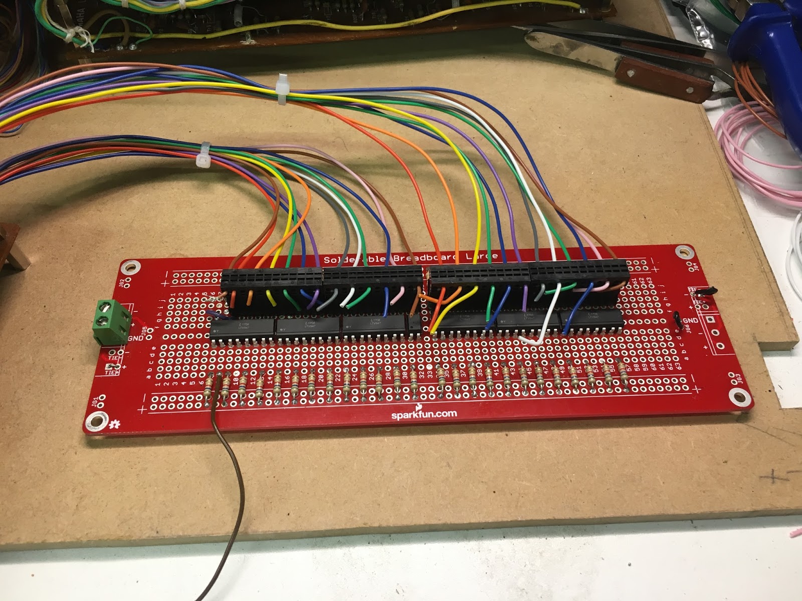
Avoiding the datasheet again I worked through a series of resistsors from 1K to 10K and measured the input current and output voltage drop. I was looking for the point where the input current is low but not so low that the output current is throttled and the voltage drop across the output collector emitter is rising.
Since taking these measure I seem to have lost the info what the supply voltage was. Was I used 9V or 12V or what? Ah well. When I go the 6K8 resistors I decided they were too high and although the voltgae drop shoudl have been relatively little i t was much higher. May be I changed the input voltage? In any caseI decided to change to 5K6 and as I had enough 'in stock' I used those instead. It was time to start building!